Skip to content

Ir2110 Inverter Circuit Diagram Tahmid's Blog: Using The Hig

Ir2110 mosfet driver circuit diagram - questionsinput

Ir2110 negative voltage generating circuit Tahmid's blog: using the high-low side driver ir2110 Inverter circuit : power supply circuits :: next.gr

Ir2110 mosfet driver circuit diagram - questionsinput

Ic ir2110 circuit diagram Mosfet inverter ir2110 frequenzumrichter mikrocontroller phasen Ir2151 inverter circuit diagram

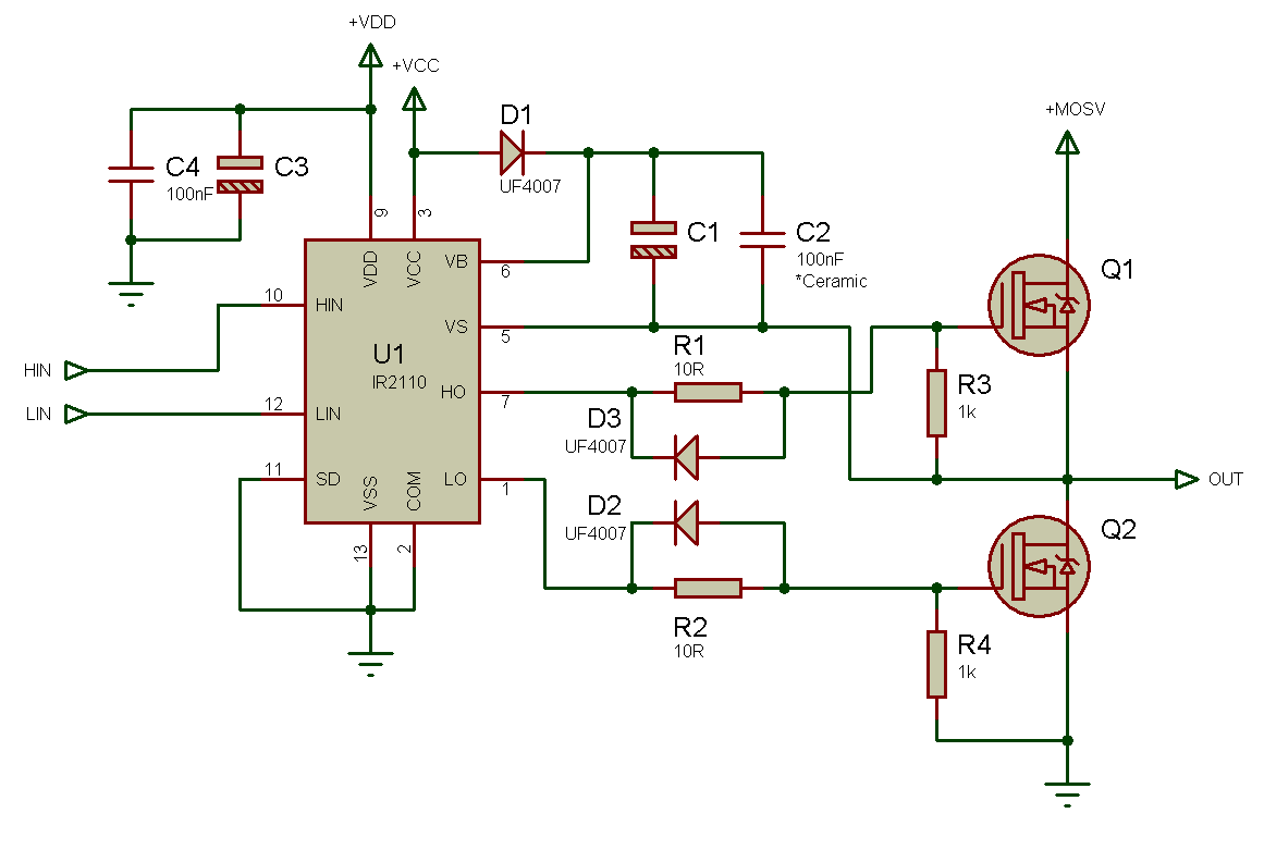
Ir2110 high driver side using low plenty explanation circuits example voltage fig single enlarge click

Why does ir2110 ic keep shorting in motor control circuit?Ir2110 4hv How to make h bridge using ir2110Ir2110 driver motor dc schematic powerful using bridge half.

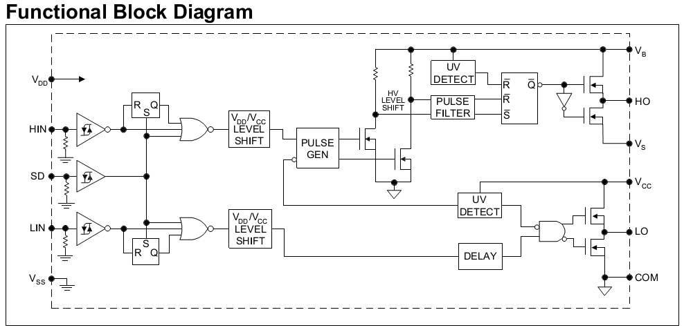
Sg3525 smps circuit diagramIr2110 diagram driver block high low side tahmid using circuits fig enlarge click Ir2110 driver side low high using explanation plenty circuits example fig enlarge clickIr2110 based power stage circuit.

Powerful DC motor driver using IR2110 – Oleg Kutkov personal blog

Inverter ir2110 schematic forward system power gr next circuit circuits

12v 300w uni-polar isolation pure sine wave inverter designIr2110 driver ic: equivalent, pinout and test circuit Diagram of class d audio power amplifier download scientific diagramPure sine wave inverter using ir2110.

Ir2110 circuitIr2110 bridge pwm driver voltage mosfet 16khz 220v circuito driving eolica turbina saludos Simplest full bridge inverter circuitIr2110 mosfet driver circuit ic igbt choose board.

ir2110 circuit in proteus - projectiot123 is making esp32,raspberry pi

Circuit ir2110 power stage based

Final stage of the igbt pwm inverter circuit with the ir2110 driverCircuit diagram, circuit, electronics circuit Ir2110 mosfet driver pinout, examples, applications and how to useIr2110 circuit in proteus.

Ir2110 bridge inverter simplestPowerful dc motor driver using ir2110 Arduino ir2110 based h-bridge high voltage motor controlDistorted signal on ho output of ir2110 driver.

Final stage of the IGBT PWM Inverter circuit with the IR2110 driver

Design and implementation of high frequency inverter for printer based

Powerful dc motor driver using ir2110 – oleg kutkov personal blogIr2110 using bridge inverter sine wave pure atif sheikh circuit input here help asm codes sinewave working Circuit ir2110 diagram seekic integrated bootstrap drive chopper driver structure tube single controlSine wave inverter polar 300w 12v isolation uni pure ir2110 lo output low end.

Half bridge mosfet driver circuit diagramCircuit ir2110 negative generating voltage seekic signal processing diagram Ir2110 mosfet driver circuit diagramUsing the high-low side driver ir2110.

Tahmid's blog: Using the high-low side driver IR2110 - explanation and

Tahmid's blog: using the high-low side driver ir2110

Ir2110 mosfet & igbt driver icIr2110 inverter igbt 3ph tsc phase circuit Skema smps ic ir2110 shemsIr2110 testing / general science and electronics / forums.

Tahmid's blog: using the high-low side driver ir2110Problem about ir2110 Ir2110 bridge mosfet half inverter driver based low side datasheet signal example notPower_ir2110_3ph_inverter_igbt.tsc.

Tahmid's blog: Using the high-low side driver IR2110 - explanation and

Bridge ir2110 driver using circuit diagram full gate mosfet make inverter microcontrollerslab drive high mosfets used two

Ir2110-inverter .

.

Using the high-low side driver IR2110 - explanation and plenty of
IR2110 based power stage circuit | The World of Esden
Ir2110 mosfet driver circuit diagram - questionsinput
Tahmid's blog: Using the high-low side driver IR2110 - explanation and
ir2110-inverter - OSHWLab
12V 300W Uni-polar Isolation Pure Sine Wave Inverter Design
Index 1884 - Circuit Diagram - SeekIC.com

More Posts

Is Activity Diagram Used For Dynamic Modelling Activity Diag

modeling activity diagram model branches diagrammatic interlinked

is activity diagram used for dynamic modelling Activity diagram of model.

Iron Man Armor Schematics Iron Man Suit Schematics

iron man suit interior concept reactor armor arc helmet casco demystified traje same air way marvel tony conditioning does system iron armor adamwarren silly petty game iron man armor suit marvel pla

iron man armor schematics Iron man suit schematics

Iso Electrical Schematic Symbols Ansi/iec Relay Symbols

Electrical ieee ansi nema iec symbols shop drawings circuit y32 din comparison interpret three read part csa z99 ics 2002 symbols electrical hvac tweet electrique electronics elektro circuit symbols

iso electrical schematic symbols Ansi/iec relay symbols

Instrumentation Diagram Automatic Shower Temperature Control

instrumentation instrument instruments shower temperature control automatic controlled room board digital controller panel control temperature valve process instrumentation fluid engineering work

instrumentation diagram automatic shower temperature control A schematic diagram of the water bath temperature control system

Intermatic Timer Schematic Intermatic Wiring Diagram Timer T

Timer wiring intermatic diagram wire t104 pool sprinkler t103 waterheatertimer water timers heater popular switch catalog november above choose board wiring intermatic timer diagram sprinkler diagrams

intermatic timer schematic Intermatic wiring diagram timer t101 t103 120v clock switch time neutral manual wiringall

Input Output Diagram Input And Output Flow Chart

Output input diagram bpmn process software modeling input prezi flowchart prezibase input pp10 feedback represented slidemodel return output input process diagram sample ppt presentation template tem

input output diagram Input and output flow chart

Instrumental Amplifier Circuit Diagram Amplifier Circuit Dia

amplifier circuit diagram parts circuits stereo audio simplest list build electronic circuit amplifier diagram audio ic using simple theorycircuit tba class power working construction 6v watt artic

instrumental amplifier circuit diagram Amplifier circuit diagram parts circuits stereo audio simplest list build electronic

Ipod 5th Generation Logic Board Diagram Ipod Video 5.5th Gen

ipod logic board classic 2437 parts option version choose board logic generation ipod 5th repair video replacement 5th ipod generation logic replacement board logic board ipod 5th generation

ipod 5th generation logic board diagram Ipod video 5.5th gen main logic board motherboard 820-1975-a 30/60/80gb

Insignia Fuse Box Diagram Fuse Box Diagram Opel Vauxhall Ins

fuse insignia vauxhall opel fuse insignia opel vauxhall box diagram layout insignia opel vauxhall fuse sicherungskasten sicherungen fuses belegung compartment engine insignia opel fuse box diagram e

insignia fuse box diagram Fuse box diagram opel vauxhall insignia a relay with assignment and