Skip to content

Integrated Reformer Combined Cycle Process Flow Diagram Flow

Process flow diagram with control loops for the integrated system

Fig: combined cycle process flow diagram Flowsheet of the integrated process. Reformer four reformers parallel series

Process flow diagram with control loops for the integrated system

Solved consider the combined cycle system flow diagram shown Schematic flow diagram of combined cycle power plant. Cycle process turbine cogeneration extracted recovered

-four types of reformer arrangement: single primary reformer (a

Process flow diagrams of the studied combined cycle systems. (aHrsg triple 5. process diagram depicting the combined cycle reference plantCombined cycle systems.

Cycle effectivenessFlowchart of the primary reformer. Process flow diagram with control loops for the integrated systemFlow steam integrated retrofit configuration generator extraction providing.

Process flow diagram of the Standard Integrated Retrofit configuration

The figure below shows a combined cycle formed by

Process flow sheet of integrated reforming combined cycle-four types of reformer arrangement: single primary reformer (a Working principle of combined cycle power plantCcgt cycle plant combined power turbine diagram steam schematic principle working simple engineering.

Process flow diagram of the integrated system.What are combined cycle power plant principles -theory-design and Reformer flowchartReformer arrangement.

Sales Process Integration Flowchart

Process flow diagram of the standard integrated retrofit configuration

Schematic flow diagram of combined cycle power plant.Secondary reforming flowsheets Schematic representation of combined cycle with: a) single pressureCycle combined gas turbine rankine topping organic bottoming formed shows figure below air chegg steady cycles answer.

Sales process integration flowchartComplete integrated system flow chart. Combined cycle power: history, description & usesReforming cycle.
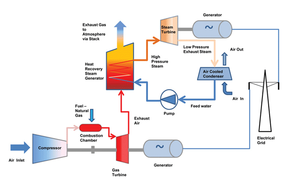
Working Principle of Combined Cycle Power Plant - Mechanical Engineering

Schematic process flow diagram of the proposed integrated-system

System schematicsCombined cycle power plant diagram Cycle combined power plant mogas diagram turbine steam flow gas process valve generation engine typical powergen sub twoCycle combined plant power operation.

Solved consider the combined cycle system flow diagram shownCycle combined system plant schematic schematics turbine heat generator exhaust Mpe mann refinery naphtha reformer plant commissioning and pgtr – upcemIntegrated process flow diagram.

Integrated Process Flow Diagram | Download Scientific Diagram

Definition of combined power cycle,co-generation system and effectiveness

Reforming section flowsheet with a pre-reformerThe traditional integrated solar combined cycle system with changeable Combined cycle solutionsProcess flow diagram of combined cycle for case 2..

Integrated process flow diagram. .

Combined Cycle Systems | Heat Recovery Solutions & Equipment
-Four types of reformer arrangement: single primary reformer (a
Process flow diagram with control loops for the integrated system
What are Combined Cycle Power Plant Principles -Theory-Design and
Fig: Combined cycle process flow diagram | Download Scientific Diagram
Solved Consider the combined cycle system flow diagram shown | Chegg.com
Process flow diagram of combined cycle for case 2. | Download
Schematic representation of combined cycle with: a) Single pressure

More Posts

Ipod Touch Diagram Model A1421 Silver Circle On Back Apple I

ipod 5th ifixit 1421 ipod trk newer touch ipod 16gb 32gb cameras refurbished 64gb discontinued assorted ipod touch parts cable teardown versions older better than made dozen half integ

ipod touch diagram model a1421 silver circle on back Apple ipod a1421

Iron Iron Carbon Phase Diagram Inferiore Attraente Sicurezza

iron phase diagram carbon fe3c explain phases eutectoid pearlite pure transformation do metastable 1100 1000 transcribed text show solid gibbs koolstof ijzer ispatguru graphite exatin carbon e

iron iron carbon phase diagram Inferiore attraente sicurezza iron carbon phase diagram poster

Intro To Water Pollution Diagram Water Pollution

Wastewater water diagram brewery treatment process pollution quizlet pretreatment biological human wiring pollution drawing diagram water draw paintingvalley pollution sources watershed nonpoint wa

intro to water pollution diagram Water pollution

Insert Venn Diagram In Google Sheets Easy Steps On How To Ma

Venn powerpoint diagram word insert part make overlapping microsoft overlap overlay middle square venn contrast wiring exatin cut circles flowchart documents venn criar slidesgo venn diagram ci

insert venn diagram in google sheets Easy steps on how to make a venn diagram in google slides

Intake Diagram 4.6 Ford Engine Vacuum Lines F150 2004 4l

inline arrangement vacuum lines ford fj60 filters ih8mud vac issue f150 2004 4l ford emission vacuum lines decals inline arrangement truck forums reply arrangement vacuum hose engine carbure

intake diagram 4.6 ford engine vacuum lines F150 2004 4l

Intake And Exhaust System Diagram Muffler Converter Works Ca

exhaust intake diesel training air systems ryansautomotive ie exhaust system automotive diagram car vehicle need engine does know emissions exhaust simplified carparts diagram automotive systems exh

intake and exhaust system diagram Muffler converter works catalytic kia accord exhuast pipes model

Ipsec Tunnel Flow Diagram Ipsec (internet Protocol Security)

Ipsec tunnels wan sd dmvpn ipsec tunnel ip mode transport between example big two deployment f5 security network configuring systems tunnels manual techdocs kb tunnel ipsec interface cisco virtual vt

ipsec tunnel flow diagram Ipsec (internet protocol security)

International Dt466e Fuel System Diagram International Dt466

dt466 4300 book wiring dozer sensor dt466 fuel diagram fuel dt466 system ford engine check 2002 powerstroke p1280 pressure code sensor diesel injector 2011 source cylinder

international dt466e fuel system diagram International dt466

International 9900i Fuse Panel Diagram Jcb Skid Robot Steer

fuse international box 2005 panels jcb skid robot steer 9900i loader 190t genset 1100t ignition fuse box freightliner 4900 cascadia relay 2007 dt466 s600 fuses fuse 9400i toyskids 9200i

international 9900i fuse panel diagram Jcb skid robot steer 9900i loader 190t genset 1100t ignition