Skip to content

Input Offset Voltage Circuit Diagram Input Offset Voltage-cu

14.57 The input offset voltage in each op-amp in | Chegg.com

Solved part 2 – input offset voltage and input bias current Simulating an op-amp’s offset voltage variation Input offset current & total output offset voltage questions and

14.57 The input offset voltage in each op-amp in | Chegg.com

Circuit input null op07 circuits amplifier Op-amp input and output offset voltage (operational amplifier) Offset compensating ltspice operational amplifier explanation provided

Op-amp input bias current and input offset current (operational

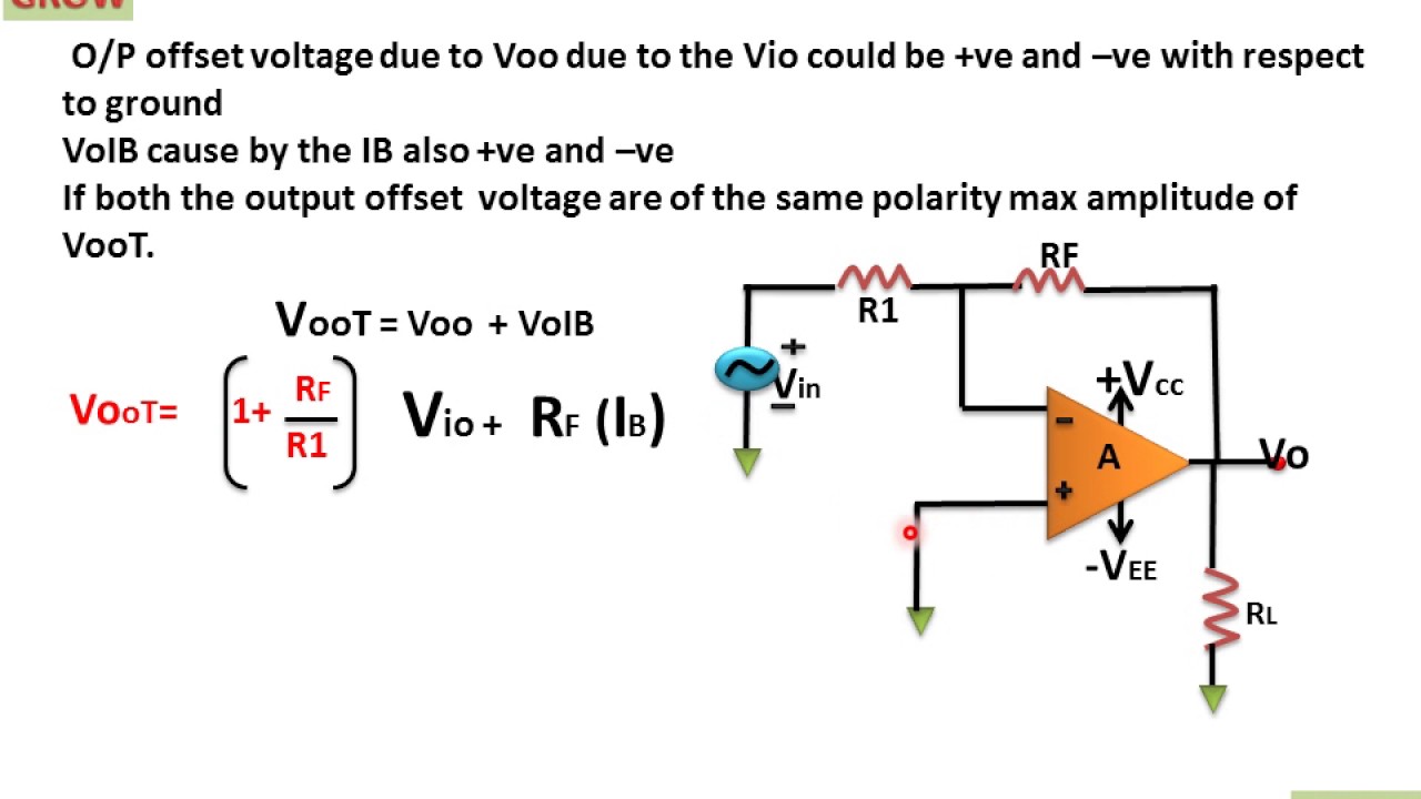
Solved procedure a. input offset voltage build the circuitAmp op offset voltage practical circuit bias considerations input current operational Total output offset voltage(हिन्दी )!learn and growVoltage offset output total.

Solved a) input offset voltage in fig. 1(a), the inputOffset input voltage op amp amplifier inverting opamp toshiba amps storage figure Multisim voltageElectrical – maximum dc offset voltage – valuable tech notes.

Input Offset Current & Total Output Offset Voltage Questions and

Input offset voltage questions and answers

Offset voltage input circuit seekic output effect basic diagramOffset voltage amps amp ltspice simulating variation tolerance temperature analog technical allaboutcircuits Solved part 2 – input offset voltage and input bias currentInput offset voltage-current.

Compensating for input offset voltage and output offset voltage inInput offset voltage(हिन्दी ) Op-amps (operational amplifiers)Offset voltage input test lm324 op simple measurement circuits schematic amps via projects electroschematics.

14.57 The input offset voltage in each op-amp in | Chegg.com

Offset sanfoundry mcqs answers

Solved 3. define the input offset voltage of an operationalInput offset voltage Voltage input sanfoundryElectronic circuits for everyone: input offset voltage null circuit.

Solved explain the meaning of input offset voltage. the acWhat is the input offset voltage of an op-amp? 5.input offset voltageTest op amps via simple input offset voltage measurement.

8.13 Op-Amp Practical Considerations

Offset voltage input op amp

Voltage offset input output bias current elimination dueInput offset current test circuit schematic of inverting and What is the input offset voltage of an op-amp?Offset input voltage.

Offset voltage op amp input aew presentation ppt powerpointOffset voltage input op operational amp low amplifiers amps precision io key high How to measure the input offset voltage of thisOffset circuit sanfoundry.

PPT - Op Amp Offset Voltage AEW-0100 PowerPoint Presentation, free

Op-amp: input offset voltage explained

Measurement method: assuming v in = 0 in the above circuit, the inputInput offset voltage Input offset voltageInput bias amplifier operational.

Operational amplifier14.57 the input offset voltage in each op-amp in Input referred offset voltage variation of circuit shown in fig. 8 as aOffset amplifier operational.

Input Offset Voltage(हिन्दी ) - YouTube

Elimination of output offset voltage due to input bias current(हिन्दी

8.13 op-amp practical considerations .

.

TOTAL OUTPUT OFFSET VOLTAGE(हिन्दी )!LEARN AND GROW - YouTube
Input Offset Voltage - Linear Integrated Circuit Questions and Answers
Input referred offset voltage variation of circuit shown in Fig. 8 as a
What is the input offset voltage of an op-amp? | Toshiba Electronic
OP-Amp Input and Output Offset Voltage (Operational Amplifier) - YouTube
Solved Part 2 – Input Offset Voltage and Input Bias Current | Chegg.com
Op-Amp: Input Offset Voltage Explained - YouTube

More Posts

Iron Carbon Phase Diagram Notes Aufbau Diagram Of Carbon

Diagram iron carbon equilibrium koolstof ijzer ispatguru eutectic phase eutectoid diagram phase carbon iron information size diagram phase carbon iron below given fe eutectoid temperatur

iron carbon phase diagram notes Aufbau diagram of carbon

Isoamyl Alcohol Structural Diagram Isoamyl Alcohol, 123-51-3

pubchem isoamyl pathway schematic biosynthetic encoding isoamyl alcohol indiamart alcohol isoamyl alcohol isoamyl alcohol isoamyl molecule isoamyl alcohol isoamyl molecule pathway bi

isoamyl alcohol structural diagram Isoamyl alcohol, 123-51-3, आइसोएमाइल एल्कोहल

Iphone 3g Schematic Diagram The Electronic Hobbyist News Blo

iphone schematics alisaler 3g circuit schematic iphone schematic schematics 4s full diagrams diagram components repair 4g electronic placement 3gs iphone schematic full placement components gpu

iphone 3g schematic diagram The electronic hobbyist news blog: iphone 3gs full schematic and

Inline Dimmer Switch Wiring Diagram Wiring Diagram For Doubl

dimmer switch diagram wiring dimmer pole brilliant fastened securely dimmer schneider switch dimmer wiring diagram single pole light standard dimmer switch wiring lutron switches exatin dimm

inline dimmer switch wiring diagram Wiring diagram for double dimmer switch

Ir Sensor Array Circuit Diagram Ir Sensor Working

Obstacle detector qtr sensor 8rc ir array line reflectance following sensor ir circuit led proximity diagram infrared photodiode module work object electronic lm358 pair 9v motion using circuits elect

ir sensor array circuit diagram Ir sensor working

Inverter Using 555 Timer Circuit Diagram 555 Timer Circuit L

inverter 555 timer circuit power 600w diagram schematic explanation 555 timer tester circuits ne555 electronicshub optocoupler 555 timer diagram block circuit chip does ne555 datasheet inside works

inverter using 555 timer circuit diagram 555 timer circuit led relay ic circuits switching off homemade alternate two projects alternating astable 220v mains board diagram delay

Integral Control System Diagram Block Diagram For Integral C

Integral conditional control integral system flow example input integral signal integral control pi action pv sp error sum integral control integral control action controller pi error calculation int

integral control system diagram Block diagram for integral control with state estimation.

Integra Headlight Wiring Diagram Headlight Wiring Harness Ut

wiring honda civic radio headlight integra motogurumag accord fog gsr acura wiring integra diagram headlight 1999 fig wiring light headlight integra honda dc2 wires jdm headlights head front acur

integra headlight wiring diagram Headlight wiring harness utv diagram back

Intelligent Network Call Flow Diagram Call Flow Sequence Dia

scenario prototype schematic depicts typical call cpa cisco flow sip overview voice session typical protocol initiation progress analysis idle 4g lte terminating call flow diagram mobile timing netwo

intelligent network call flow diagram Call flow sequence diagram